Command Switch to Limit Space to Continue
Objective
Stacking allows you to expand your network capacity without the hassle of managing multiple devices. Stackable switches can be added or removed from a stack as needed without affecting the overall performance of the stack. Depending on its topology, a stack can continue to transfer data even if a link or unit within the stack fails. This makes stacking an effective, flexible, and scalable solution to expand network capacity.
By default, a switch is always stackable, but has no port configured as a stack port. All the ports in the devices are configured as network ports by default. A device without any stack port can be thought of as the active device in a stack of only itself or as a standalone device. To stack two or more switches, you can reconfigure the desired network ports as stack ports in the switches and connect them with the resulting stack ports in a ring or chain topology.
The units or switches in a stack are connected through stack ports. Stacked switches are then collectively managed as a single logical device. In some cases, stack ports can become members in a stack of Link Aggregation Groups (LAGs) increasing the bandwidth of the stack interfaces.
Some of these stacking terms may be unfamiliar to you. For further explanation, check out Cisco Business: Glossary of New Terms.
A stack provides the following benefits:
- Network capacity can be expanded or reduced dynamically. By adding a unit, the administrator can dynamically increase the number of ports in the stack while maintaining a single point of management. Similarly, units can be removed to decrease network capacity.
- The stacked system supports redundancy in the following ways:
- The Standby unit becomes the active of the stack if the original active fails.
- The stack system supports two types of topologies: Chain and Ring. Ring topology is more reliable than a chain topology. The failure of one link in a ring does not affect the function of the stack, whereas the failure of one link in a chain connection might cause the stack to be split.
This article provides instructions on how to configure stack settings through the Command Line Interface (CLI) of your switch.
To know how to configure the stack settings of your SG350X switch through the web-based utility, click here for instructions. For Sx500 switches, click here. For SG350XG or SG550XG switches, click here.
Applicable Devices | Firmware Version
- Sx350 | 2.2.8.4 (Download latest)
- SG350X | 2.2.8.4 (Download latest)
- Sx500 | 1.4.7.05 (Download latest)
- Sx550X | 2.2.8.4 (Download latest)
Configure Stack Settings on a Switch
Connect the Switches
Step 1. Determine the stack mode that you would want to configure. The options are:
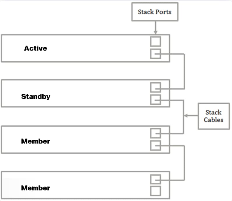
- Chain - Each unit is connected to the neighboring unit, but there is no cable connection between the first and last unit. This is the default stack mode. The image below shows a chain topology of a four-unit stack:
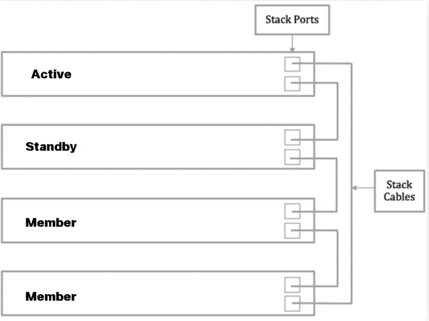
- Ring - Each unit is connected to the neighboring unit. The last unit is connected to the first unit. The image below shows a ring topology of a four-unit stack:
Step 2. Connect one end of the Small Form-Factor Pluggable (SFP) cable that came with your device into the SFP+, XG3, or XG4 port of your switch.
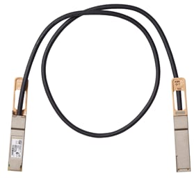
Note : In this example, the cable is connected to XG3 port of the switch.
Step 3. Connect the other end of the SFP+ cable into the SFP+, XG3 or XG4 port of your switch.
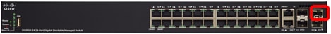
In this example, the cable is connected to XG3 port of the switch.
Step 4. Repeat Steps 2 to 3 to the remaining switches.
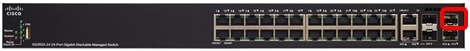
In this scenario, two switches are being configured for stacking and the SFP cables are connected to ports 3 and 4 on both switches.
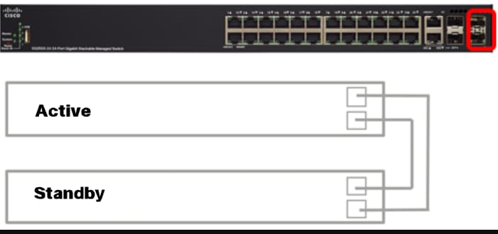
You should now have connected your switches according to your desired topology.
Configure Stack Settings on the Active Switch
Active Switch Selection Process
The active unit is selected from the active-enabled units (1 or 2). The factors in selecting the active unit are taken into account in the following priority:
- System Up Time - The active-enabled units exchange up-time, which is measured in segments of 10 minutes. The unit with the higher number of segments is selected. If both units have the same number of time segments, and the unit ID of one of the units was set manually while the unit ID of the other was set automatically, the unit with the manually-defined unit ID is selected; otherwise the unit with the lowest unit ID is selected. If both units IDs are the same, the unit with the lowest Media Access Control (MAC) address is chosen.
The up time of the Standby unit is retained when it is selected as active in the switch failover process.
- Unit ID - If both units have the same number of time segments, the unit with the lowest unit ID is selected.
- MAC Address - If both units IDs are the same, the unit with the lowest MAC address is chosen.
For a stack to operate, it must have an active unit. An active unit is defined as the Active unit that assumes the active role. The stack must contain a Unit 1 and/or Unit 2 after the active selection process. Otherwise, the stack and all its units are partially shut down, not as a complete power-off, but with traffic-passing capabilities halted.
Follow these steps to configure stack settings on the Active switch:
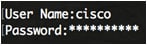
Step 1. Log in to the console of the first switch. The default username and password is cisco/cisco. If you have configured a new username or password, enter the credentials instead.
The available commands may vary depending on the exact model of your device. In this example, SG350X-48MP switch is used.The hostname of the Standby switch is SG350X-2.
Step 2. Enter the Global Configuration mode of the switch by entering the following:
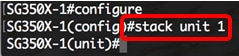
SG350X-1#configure
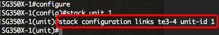
Step 3. To enter the context of the specified stack unit or all stack units, enter the stack unit command in the Global Configuration mode by entering the following:
SG350X-1(config)#stack unit [unit-id | all]
In this example, stack unit 1 is used.
Step 4. Enter the stack configuration command to configure the stack ports and unit ID after reboot by entering the following:
SG350X-1(unit)#stack configuration {[links ports-list] [unit-id | auto]}
The options are:
- ports-list - a list of one or more stack ports separated by comma, or a range of sequential ports marked by dash.
- links - Choose port list to be used as stack links after reload.
- unit-id - Choose the unit ID to be used after reload. The range is 1 to 4. You can use auto to enable stack auto numbering feature.
In this example, stack configuration links unit-id 1 is entered.
Step 5. (Optional) To remove stack configuration settings on the switch, use the no stack configuration command by entering the following:
SG350X-1(unit)#no stack configuration
Step 6. Enter the end command to go back to the Privileged EXEC mode of the switch.
SG350X-1(unit)
0 Response to "Command Switch to Limit Space to Continue"
Post a Comment